Numark M2 Crossfader Replacement?
The Numark M2 Crossfader is Shit.
Lets be real. The Numark M2 is a suckers mixer, it was made for people to get into DJ’ing and drop it like a hot potato. The mixer may be ok, I love the Numark DXM’s, but this one just feels like shit from the 90’s with the shit quality Gemini fader to match.
For $1 more they could of incorporated their “D-Type” crossfader which works great.
Down to the style of wire and plug they used, you can tell that they made this to be difficult to mod and a throw away mixer. This is a shame, and leaves a sour taste towards Numark (again) after them making so much great stuff in between their failures.
Either which way. The Numark M2 is one of the best selling beginner mixers (no idea why), but the crossfader is shit. So lets fix this issue together!
Numark M2 Crossfader
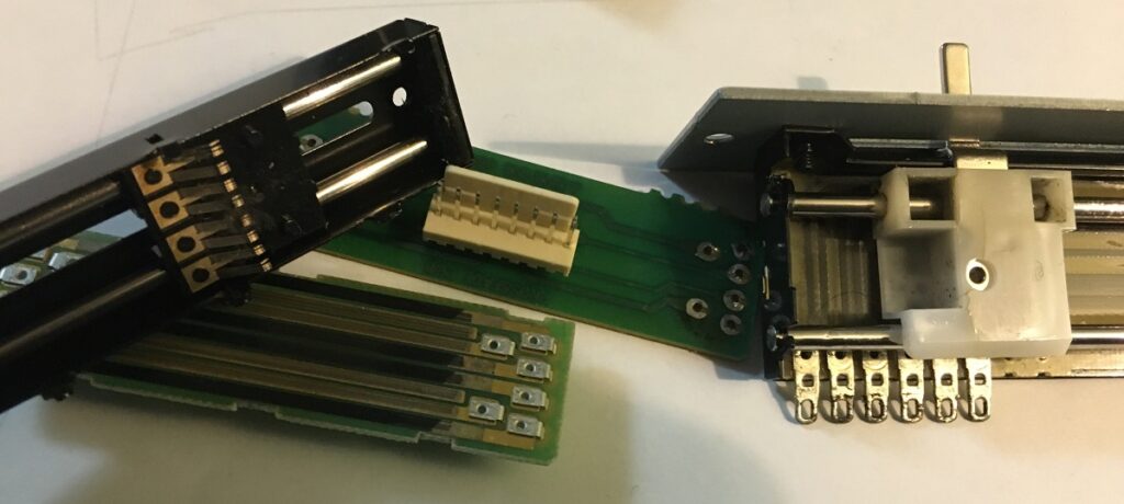
So after taking apart the M2 crossfader on the left and the “D-Type” on the right. It seems like the M2 was overkill and designed not to fail, so why does it fail so quick? Once removed from the board it feels and glides like a Rane on rails. My guess is the heavy duty prongs made it stiff and wear out quick. Besides for that it probably would of been a great fader.
The Numark “D-Type” fader is a pretty standard Alpha VCA crossfader that can be found in a lot of standard mixers (Stanton, Vestax, etc.) and will mount up fine to any standard mixer plate. Any crossfader around 100Kohms will work fine and it really just comes down to wiring it in.
Numark M2 Crossfader Wiring
I have not included instructions on how to open the mixer, but hopefully if you are jumping into this diy, turning a few screws is not an issue! You will need the following:
-Crossfader
-Copper Wires. Use your imagination, but old car wiring harnesses are filled with different colors, sizes, lengths and options.
-Male header pins. A large quantity of 2.54 mm Arduino Connector strips can be had for around $5 on the interwebz.
-Heat Shrink tubez.
-Of course some soldering equipment and soldering Skillz!
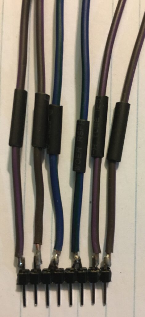
Most crossfaders/faders will be anywhere between 3-9 pins. Which leads to a lot of confusion when it comes to wiring in a new fader. It really just comes down to channel 1, channel 2, and the wiper (fader part). The “D-Type” fader has 6 pins, whereas the original M2 crossfader connection has 8 pins. On the connection to the mixer (male header above) the four pins in the middle have been bent together in pairs for the wiper (ground) wires going into the crossfader. These two wires are now the left, right fade wipers.
the remaining pins on the left and right of the ground pins represent the left and right channels. I really should of drawn out a diagram, but the picture below should help with the correct orientation of the wires and how it should be plugged into the mixer.
From trial and error I came to the final conclusion for the pins coming out of the mixer as:
Pin 1: Channel One Left
Pin 2: Channel Two Left
Pin 3+4: Ground
Pin 5+6: Ground
Pin 7: Channel Two Right
Pin 8: Channel One Right
From there you will just need to match the wires to the crossfader that you intend to use.
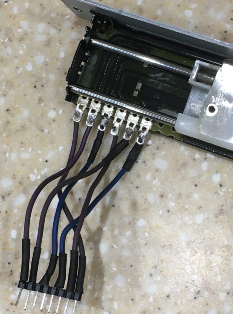
Crossfader Possibilities are Endless!
At the end of the day you could de-solder the original wires from the board and add your own 6-pin connection, wire it into 3 wires, wire in a pro fade x, etc. Get crazy!
You May Also Like
Cleaning Yellowed Knobs, Buttons, & Controls for Roland VS-890 VS-880
August 29, 2021
M-Audio Axiom 49 Keyboard Blue Screen of Death!
April 29, 2024