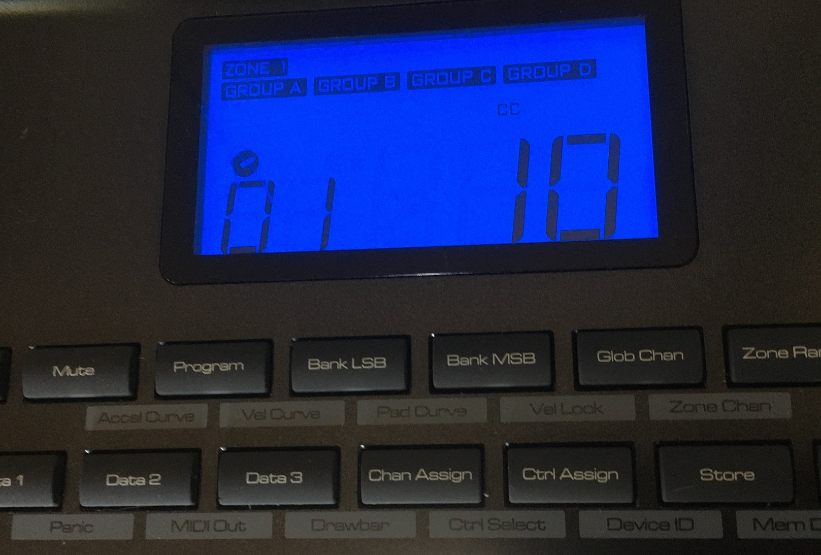
M-Audio Axiom 49 Keyboard Blue Screen of Death!
Personally I think the Axiom 49 and Axiom 25 are the best and most robust midi controllers out there. The original version just keeps trucking!
A while ago grabbed a Axiom 49 from the good for a steal at $20 but to my dismay this mofo came with the infamous “Blue Screen of Death”! Until now I have just let it wrought in the pile of dead keyboards.
If you’re encountering the dreaded “Blue Screen of Death” issue with your Axiom 49 keyboard, it may be time to replace the microprocessor on the main board. This may not be the end all fix, but according to the interwebz it seems to work for most.
You are going to need an understanding of removing and soldering a surface mount chip. I have never owned one but “reflow stations” would probably help in this situation. I personally have learned to burn the chip off high and remove the individual prongs with solder wick, clean the pads and add a fresh ball of solder to each.
That being said you will need the following:
- Phillips Screwdriver Set
- Replacement Microprocessor.
- Soldering Station and Solder: A decent quality soldering iron (even a clone) and solder are essential for surface mount soldering; or a Reflow Kit (optional but recommended).
- Desoldering Wick: I like to get the wick loose and full of flux, and fully heated up before I ever touch the solder joint. You’ll also need this to remove excess solder from the board, making way for the replacement microprocessor.
Opening the Axiom 49 (Disassemble)
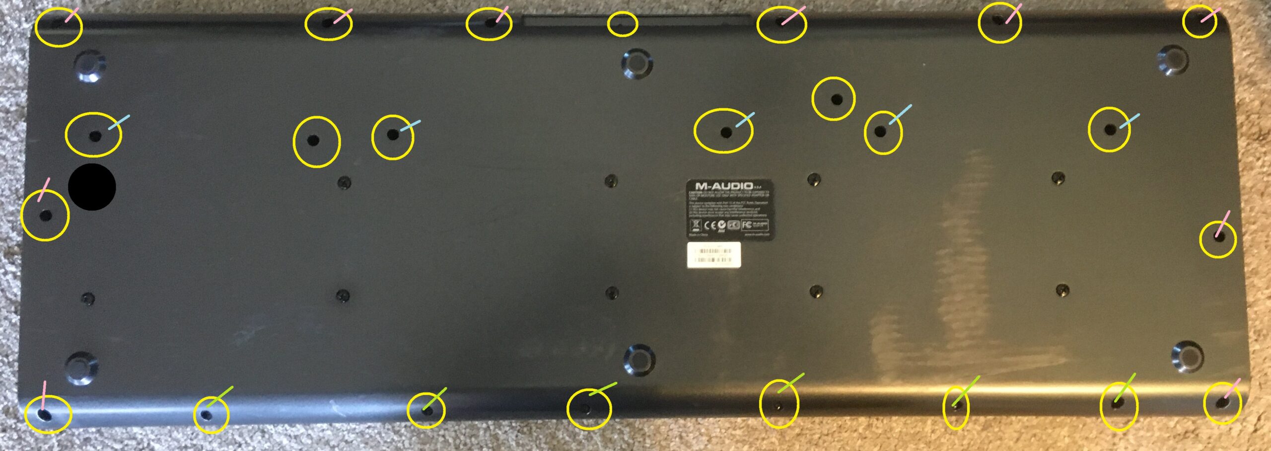
Above is an image of all the screws that need to be removed to open the case. I tried to mark the colors of the like screws incase someone stumbles on to this article after accidentally removing them without keeping track.
The best advice I can give is to take a small piece of cardboard, dot the screw placement, and screw them into the cardboard as you remove them from the keyboard.
Once all the screws are removed you can flip the keyboard over and gently giggle the shell loose.
Giggle like a fat girl, Wiggle like a fat girl, let me see that a$$ while I fap to a fat girl…
There will be a ground cable going from the main board to the top shell, loosen that screw so the ground wire can slide out (no need to remove the screw).
At this point you should be able to rest the top shell against an object or lay it flat. The main board is directly above the key bed and all of the connections will need to be removed.
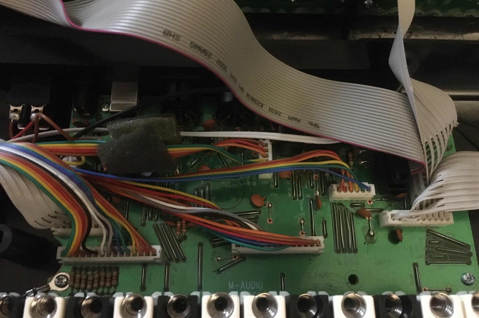
A gentlemen’s wiggle and a slight tug should release the wire connectors. The connectors and wire lengths are all different so it shouldn’t be hard to tell where they go when reassembling the unit, but if this is your first rondeau in a situation like this marking the connectors or taking pictures will help.
Once all the connectors are out, the yellow circles show the screws that need to be removed. All the screws are the same size but keep in mind that the bottom left and top right have ground cables that will need to be reconnected.
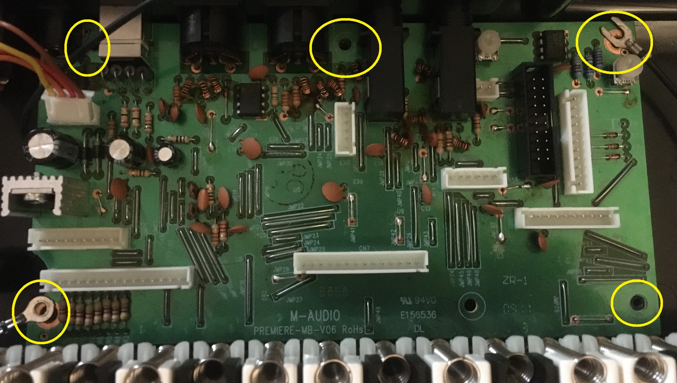
Replacing the Chip
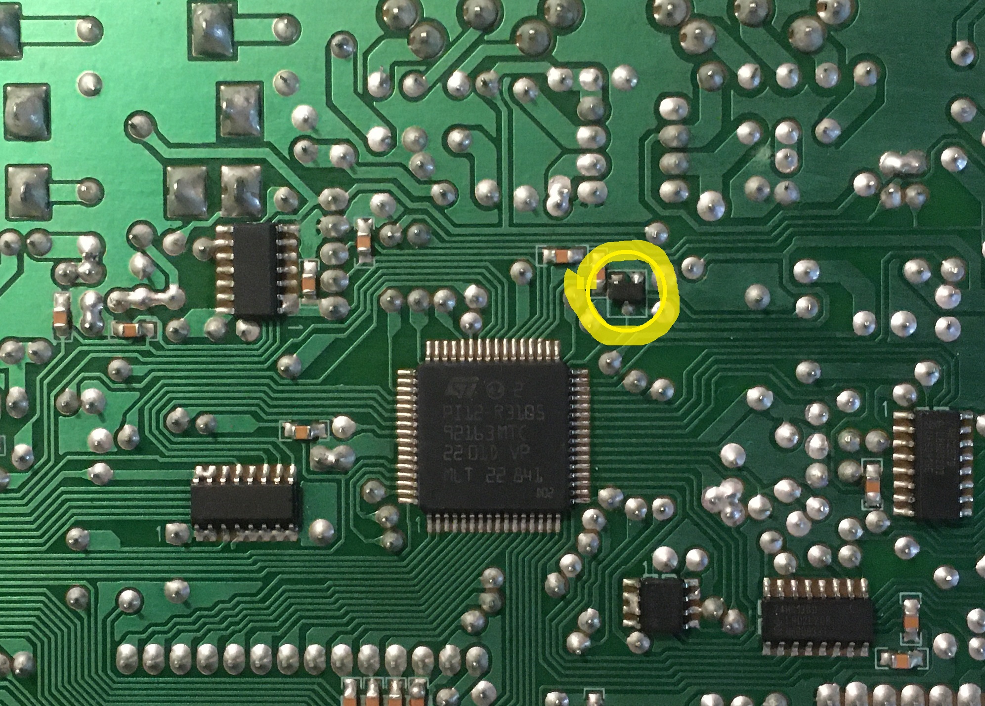
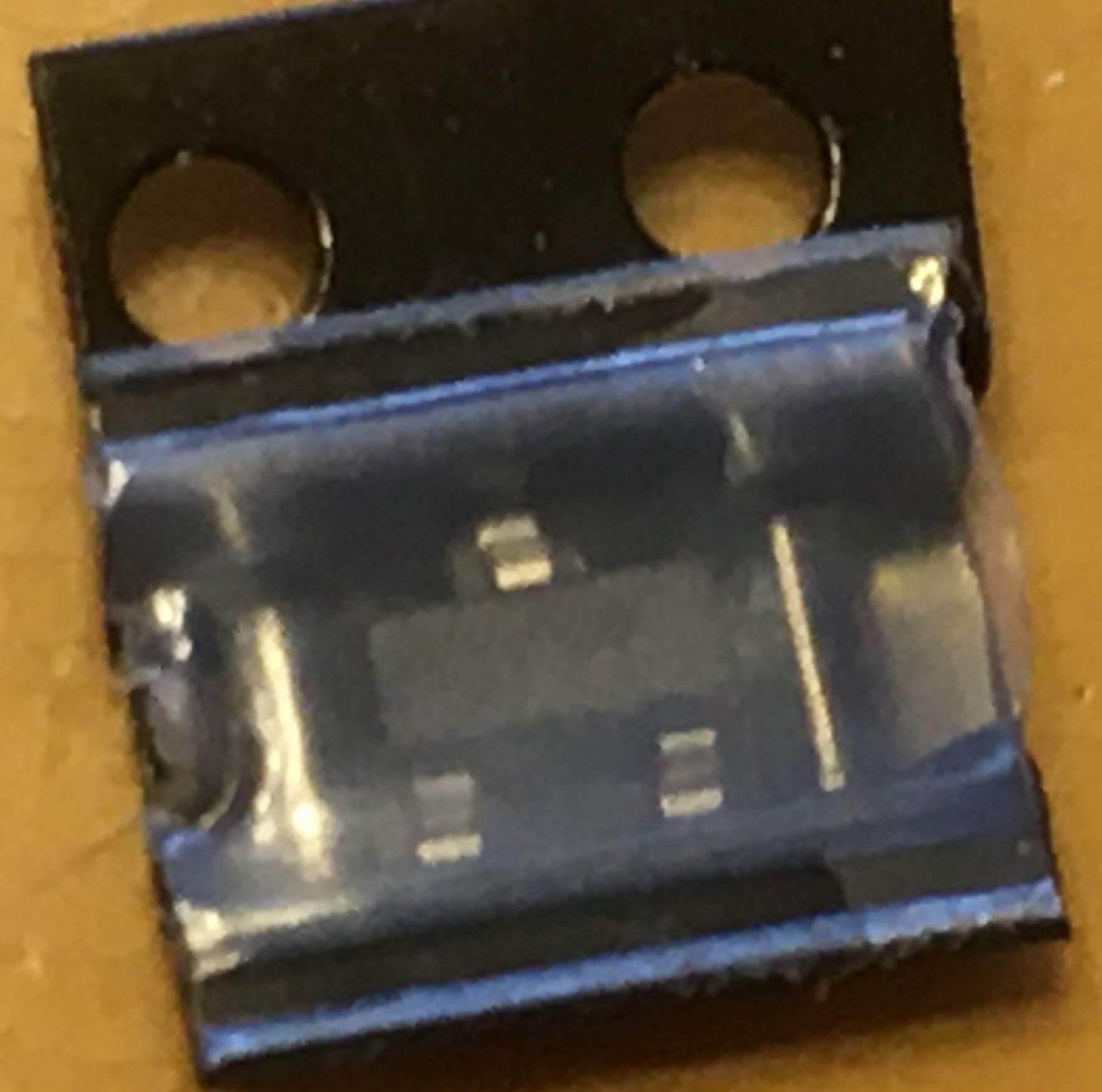
Once all the connections and screws are removed the board can easily be removed from the base of the keyboard. Flipping over the board you will see the microprocessor picture and circled in yellow above. It is probably about 3×1.5mm at most.
As mentioned above “I like to get the wick loose and full of flux, and fully heated up before I ever touch the solder joint.” You’ll also need this to remove excess solder from the board, making way for the replacement microprocessor.”
A few quick holds to the board should wick away the solder, after that I just softly burn away the top of the chip until it it can be removed piece by piece. This is the technique I have used to replace the color of LEDS on tons of machines and I have yet to burn a board or solder pad off. But to each their own.
Once the chip is off, and pads are wicked clean, a tiny ball of solder is nice to add.
Holding the new chip in place, quickly heat the solder to the chip tabs.
Look around the board for any broken solder joints. The resistor on the left side of the yellow circle had a small crack. So reflow them if needed (maybe that was the problem all along?).
TEST THE KEYBOARD BEFORE PUTTING IT BACK TOGETHER!!
I have made this mistake way to many times!
Once you have the board screwed back in and all groundwires and connections attached. Properly replace the top and hold it on with rubberbands or whatever.
If you plug it in and your screen works again you are almost there. If it doesn’t then I can’t help you.
Plug into your favorite program and test out all the keys, buttons, pads, etc. because if any of them are not working now is the time to replace or re-carbon them.
If all is well, then screw it back together and rejoice that your Axiom lives on!