Boss DR-202 Refurb, ReCap, & Backlight LCD Mod
Bought another “working” DR-202 with a broken screen. It arrived completely dead and was thrown into my crap gear pile for the last year. As I have nothing better to do, why not try to revive it?
Full Disclosure: Electronics can fry themselves and you very easily. All of the following will be done at your own risk and for starters the service manual can be found here Boss DR 202 Service Manual
Cleaning
Now I am going to leave this to your imagination. If you don’t know how to take apart a machine and clean it out the rest will probably pretty daunting.
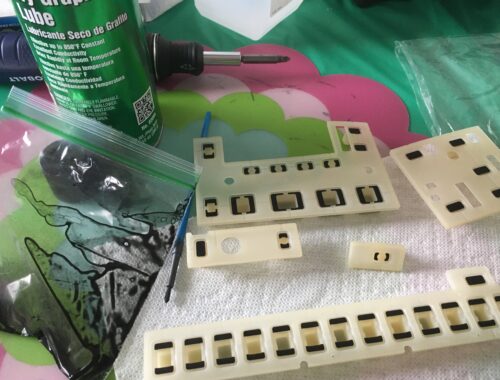
For this unit, I disassembled, soaked and scrubbed the pads and casing, with warm water, dish soap and a soft sponge (I use an old toothbrush to clean any grime between the pads). All of the pads seemed to be responsive as this Dr. 202 seemed pretty unused, so no need to paint them with carbon.
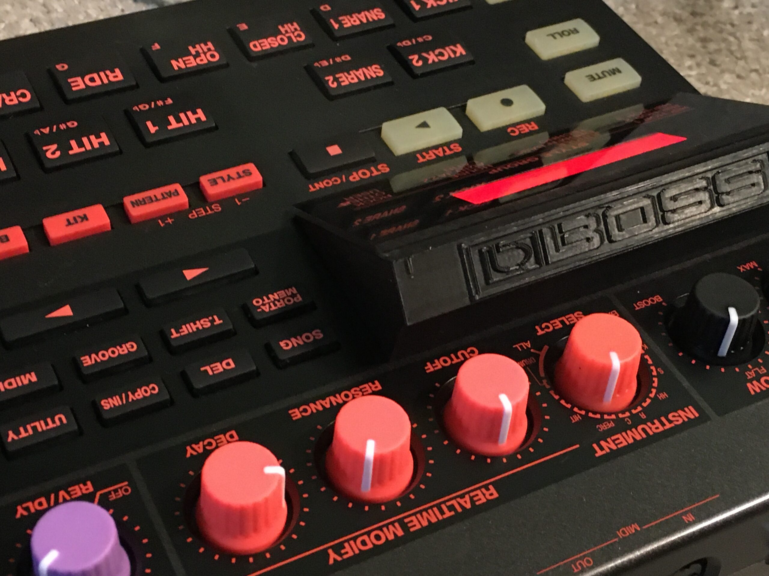
ReCapping the Boss DR-202
While modding this DR-202 and opening others I noticed that some capacitors were all marked with a red dot on top. Your machine will probably be the same. Pretty sure all the red dotted capacitors have to do with output and audio flow, so if you are going to swap any that would be a good place to start.
I seemed to have a sh*t ton of all of the capacitors that were in the machine with the exception of the 470uf 16V caps for the power. Will this change the sound? Who effin’ knows. If planning on doing this it would be recommended to just purchase and replace all of the capacitors as they are cheap, 20 years old, and probably past their life span anyways
The following is needed:
2x 470uf 16v ( I didn’t have these)
1x 1uf 50v
1x 220uf 10v
4x100uf 6.3v
5x 47uf 16v
13x 10uf 16v
Do not take this as gospel as manufacturers change specifications mid production, this is what was in my unit, but seeing how I had so many of these caps already, I am guessing they are pretty standard across the Boss line as I have capped a few other machines which would explain why I have so many of these.
The top two on the right are for the power (470 16v) which I didn’t have, these should be replaced for clean power.
So you don’t lose track, do all of the same values, then move onto the next.

Make sure to clip all the capacitor legs and clean the board of all residue. Might as well change out that old battery too.
Edit: The machine does sound cleaner. Not as “hazy” as before.
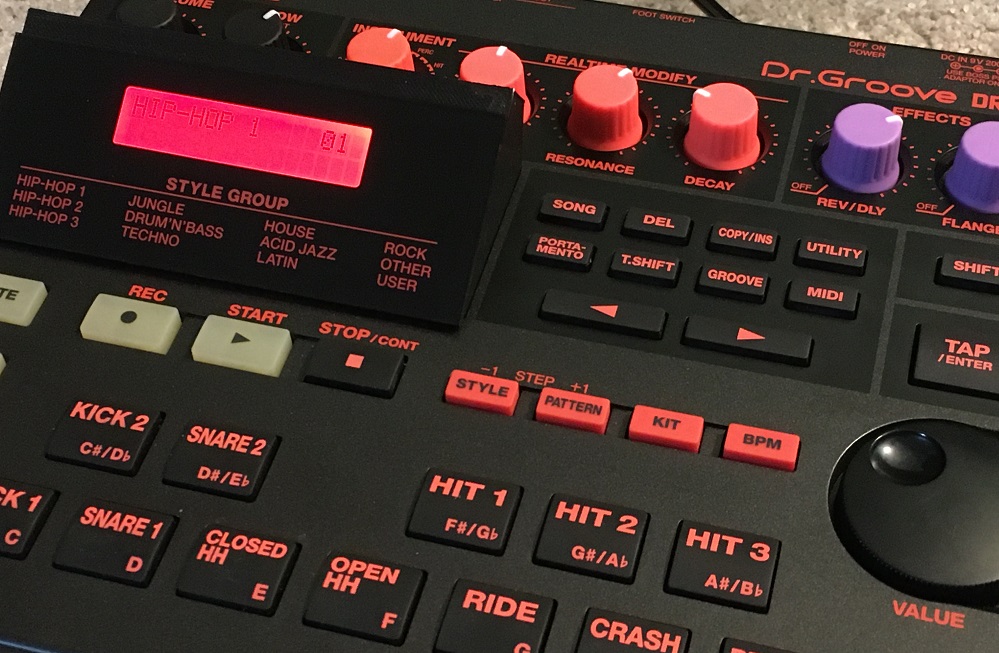
DR. Groove 202 Backlight
A few ways to go about this. The method of adding a backlight to the original screen just sounds bad to me so I have never tried that. Personally, I think wiring in a new LCD is the way to go. This is your machine so go as overkill or sloppy as you want.
You will need the Following:
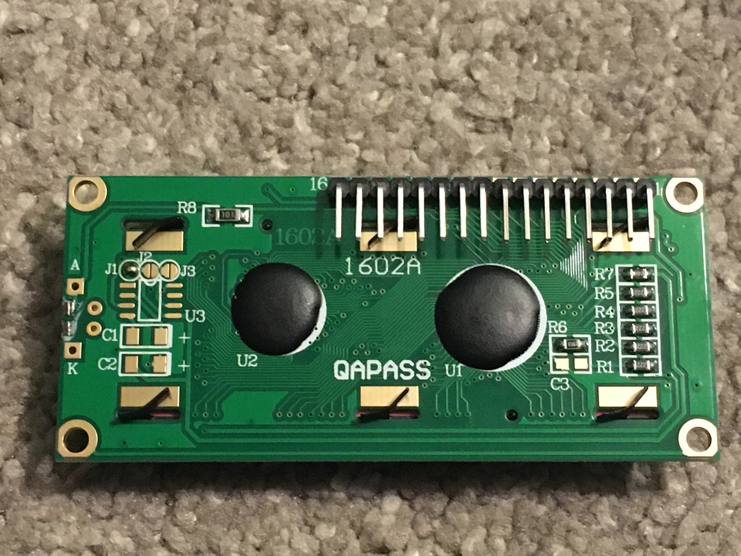
-16×2 Display 5V 1602A. These are around a few dollars each and come in a variety of colors. I have always bought the ones with the solder pads on top, but if you are designing your own tilted display stand like pictured, the ones with the pins on the bottom would be easier to squeeze in.
-Thin Wiring. (see additional edit below) Computer IDE cable or old iphone/USB charging cables pulled apart. As mentioned in another post a good source for wiring is an old car harness. They have tons of different sizes and are usually good quality. I went overkill on this one with the wiring, but after spending 20+ hours somehow bringing it back to life, designing the display stand and re-capping the machine, I really did not want the wiring to be an issue if I had to re-troubleshoot problems.
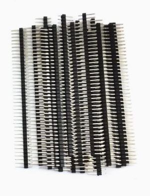
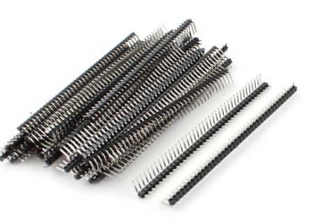
-Arduino Header Pins. These are optional but they make the install easier and are cheap. They also make it so you can swap out the display easier if you want to try out a few colors. Purchasing a set with Male, Female, & 90 degree Male strips should be good.
-470 ohm resistor
-Solder, Solder Wick, Flux (soldering tools).
-Heatshrink Tubing
Edit – While searching for pictures I found “ELEGOO 120pcs Multicolored Dupont Wire 40pin Male to Female, 40pin Male to Male, 40pin Female to Female Breadboard Jumper Wires Ribbon Cables Kit” on Amazon for like $7. I think this would be the easiest way to go.


Backlight Wire/Screen Soldering
The connection (CN3) on the main board that the original screen ribbon plugged into will need to be de-soldered. Soaking up the old solder with a wick should help it come out pretty easy. These are tiny traces, so make sure you do not pull or overheat them, pulling them from the board will create a whole new world of problems.
For the wiring, the “ELEGOO” male to either (the other side will probably need to be cut off and stripped) with a 90 degree header pin strip would be easiest. The male to female ones would be perfect, but I think those plastic connections are a little to bulky to fit together where the original CN3 connection was, but worth a try, and the other side (female) would slide nicely onto your LCD header.
As mentioned I went a little overkill by pulling pins out of a female header and soldered them on to the individual wires. Followed by soldering the the other ends to a female header strip (you could solder them directly to the display if wanted). Don’t forget your heat shrink to guarantee none of them are touching each other.
Note-I did 14 wires, then realized it’s easier to do all 16 together and just make the wires for 15 & 16 extra long as they will be used for lighting up the display.
Below (clip images for larger pictures) shows the wires connected to pins on one side and to the female header on the other side. The 90 degree header can be soldered into the Display.


Following the schematic below originally posted on syntaur forum shows the pin count and how to match up the wires from the harness to the holes for soldering. Double triple check your wires and count as you go as it’s easy to swap up the numbers.
For additional reference the original DIY links are below.
syntaur forum for reference and additional pictures.
Original DIY by Celeron55

Boss -> LCD
1 -> 3
2 -> 2
3 -> 1
4 -> 14
5 -> 13
6 -> 12
7 -> 11
8 -> 10
9 -> 9
10 -> 8
11 -> 7
12 -> 6
13 -> 5
14 -> 4
Connecting the Backlight
Pins 15(A) & 16(K) on the LCD will illuminate the screen.
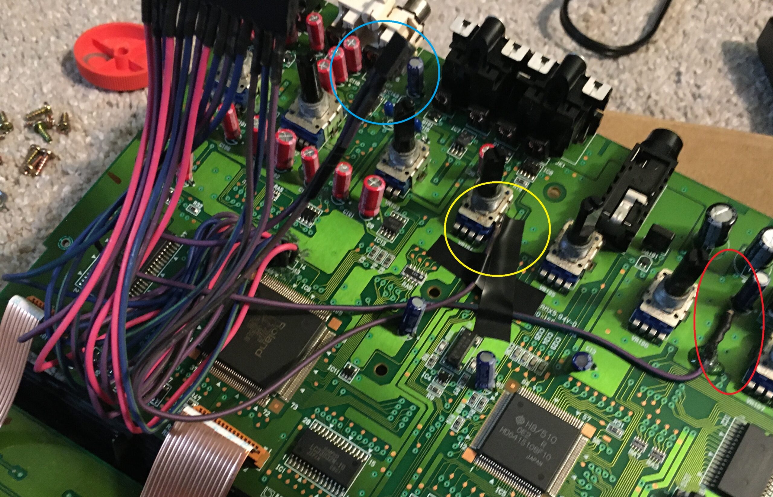
Pin 15(A) Solder your 470ohm resistor to the end of your harness wire and cover in heatshrink. Now the cleanest I have found to connect it to the board is to wick the solder from the capacitor located at C31 (100uf 6.3v) and you should be able to work a leg from your 470ohm resistor into the hole of the positive side with the capacitor leg (don’t forget to re-solder the capacitor and resistor leg back to the board). See the red circled area in the picture below.
Pin 16 (K) can be directly soldered to the side of a potentiometer for ground. See yellow circle in picture below.
The blue circle is the extra little 2 pin harness, but again I would recommend just making a 16 pin harness in the first place.
A little dab of hot glue or electrical tape will keep the wires stationary on the board. (click pictures for larger resolution)


At this point if you plug it in, everything should light up and work (the ribbon cables from the top board will need to be plugged back in). If not, start checking all of your wires and start praying that you didn’t just turn your $300 drum machine into a paperweight!
Mounting the display
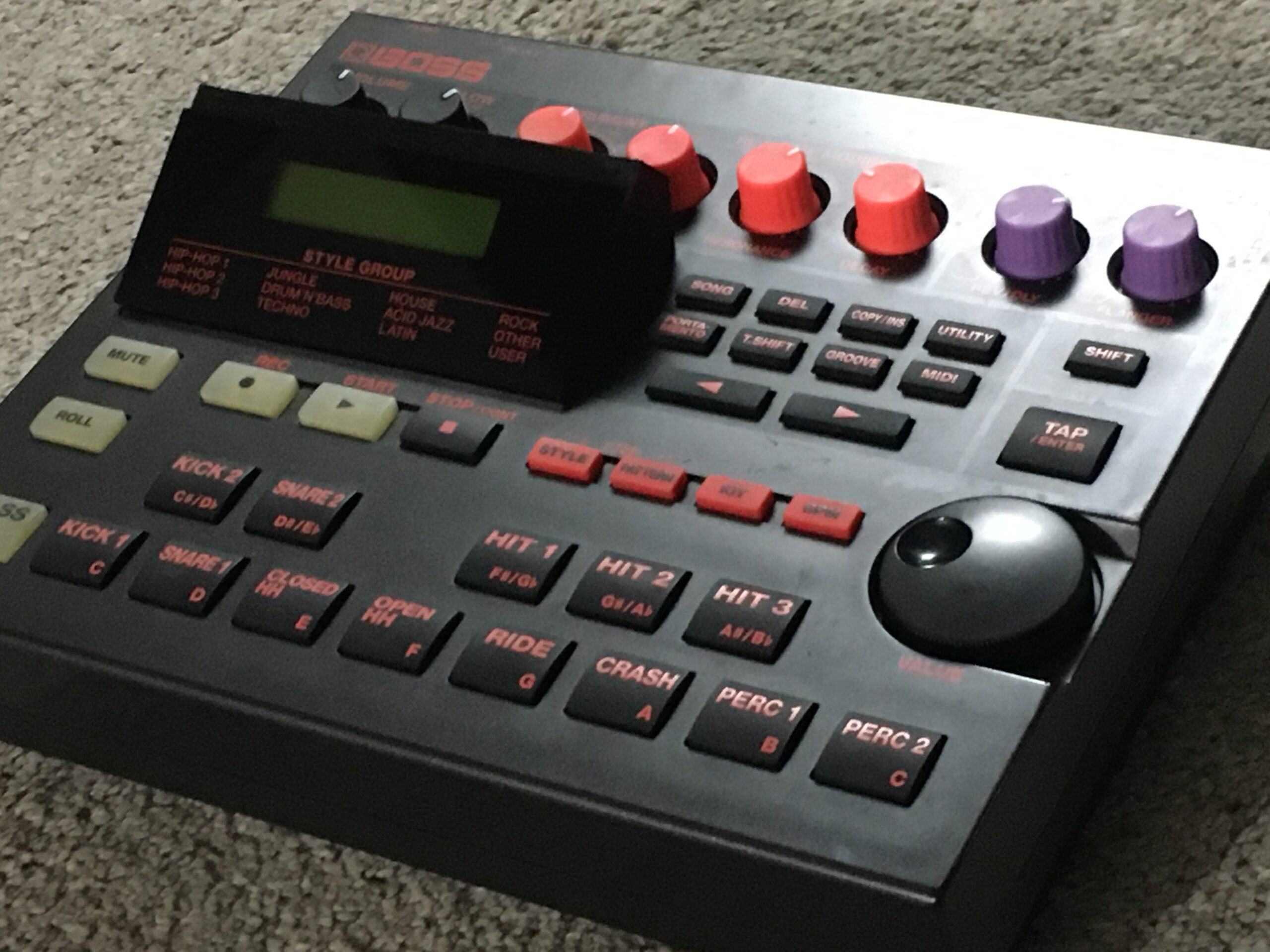
This one you are kind of on your own as I decided to make a little titled stand. On a previous unit I remember just cutting the casing a little larger to accommodate for the new LCD and I know there is a picture on the interwebz and it can just be attached to the casing with hot glue. New double stick tape can be used to reattach the “Style Group” window if needed. Just make sure everything is in correct orientation before gluing/stinking it all down.
Feel free to leave comments or any questions.


5 Comments
Nancy
Nice work!
jose
nice job! thanks a lot for sharing!
Alan
May I know :
How many watt of the 470 ohm resistor ?
Thanks
admin
Hi. I just use the little 1/4th watt ones that would come with LEDs.
Alan
Thanks, ADMIN.